How to Choose VMC Table Size and Axis Travel for Different Workpieces
Views: 0 Author: Site Editor Publish Time: 2026-08-25 Origin: Site
- 1. Start With the Finished Part, Not the Machine Specification
- 2. Why Table Size and Axis Travel Are Not the Same Thing
- 3. Add Fixture Size Before Calculating Required X and Y Travel
- 4. Calculate Z-Axis Requirements From the Entire Tooling Stack
- 5. Table Load Capacity Matters for Heavy Fixtures and Multiple Parts
- 6. Do Not Oversize a VMC Without a Production Reason
- 7. Consider How Many Parts Will Be Loaded per Setup
- 8. Allow Reasonable Capacity for Future Workpieces
- 9. Match Travel With Spindle and Cutting Requirements
- 10. Use Representative Part Drawings Before Making the Final Decision
- 11. FAQ
- 11.1 Should VMC axis travel be larger than the workpiece?
- 11.2 Is a larger VMC always better?
- 11.3 How do I determine the required Z-axis travel?
- 11.4 Should fixture weight be included when checking table capacity?
- 11.5 How much extra machine capacity should I leave for future production?
- 11.6 Can two VMCs with the same travel perform differently?
- 12. Conclusion
When manufacturers select a vertical machining center, it is easy to focus on spindle speed, machine price, or maximum axis travel. In actual production, however, the relationship between the workpiece, fixture, machine table, and available X/Y/Z travel often determines whether a machine is truly suitable.
A machine that is too small can restrict tool access, fixture design, and future part capacity. A machine that is much larger than necessary may increase equipment cost, floor-space requirements, energy consumption, and non-cutting movement without improving productivity. The objective is therefore not to purchase the largest machine available, but to match the usable machining envelope to the real production process.
Start With the Finished Part, Not the Machine Specification
Before comparing CNC machine specifications, manufacturers should collect representative workpiece drawings from current and expected future production. These drawings should include overall dimensions, machining features, material, tolerances, and the surfaces that require milling, drilling, boring, or tapping.
For vertical machine center selection, three basic workpiece dimensions should be identified first:
Maximum workpiece length
Maximum workpiece width
Maximum workpiece height
These dimensions provide a starting point, but they should never be compared directly with machine travel alone. The fixture, clamps, tool approach, and safety clearance all occupy additional space.
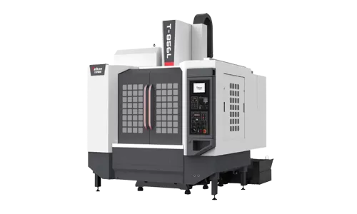
For example, a 700 mm-long component does not necessarily fit comfortably into a machine with exactly 700 mm of X-axis travel. The fixture may require locating blocks and clamping areas beyond the ends of the part, while certain machining features may require the spindle to travel past the edge of the workpiece.
Why Table Size and Axis Travel Are Not the Same Thing
Machine table dimensions describe the physical surface available for supporting the fixture and workpiece. Axis travel describes how far the machine can move the cutting tool relative to the part.
These two specifications are related, but they are not interchangeable.
A large table can provide enough physical space for a fixture while the available axis travel may still limit which areas of the workpiece can be machined. Conversely, a machine may provide substantial axis travel while the usable fixture area is restricted by table dimensions or T-slot arrangement.
When comparing machines, manufacturers should therefore ask:
Does the entire fixture fit securely on the table?
Can all required machining features be reached?
Is there enough room around the part for clamps?
Can the spindle reach beyond the workpiece edges when required?
Will the fixture interfere with machine guards or tool movement?
Evaluating these questions before machine purchase can prevent problems that only become visible after production tooling has already been designed.
Add Fixture Size Before Calculating Required X and Y Travel
A fixture may be significantly larger than the component itself. Vises, hydraulic fixtures, locating plates, rotary devices, and multi-part fixtures can all increase the actual space required on the table.
For simple single-part machining, the difference may be relatively small. In batch production, however, manufacturers may want to load multiple components on one fixture to reduce loading frequency and increase machine utilization.
Suppose a factory wants to machine four parts in one setup instead of one. The required table area can increase dramatically even though the individual workpiece remains unchanged.
This is especially important when planning future automation. Robotic loading, pallet systems, or dedicated production fixtures may require more usable space than a conventional manual setup.
Instead of asking only, “Can this machine produce the part?” manufacturers should ask, “Can this machine support the production method we intend to use?”
Calculate Z-Axis Requirements From the Entire Tooling Stack
Z-axis selection is sometimes underestimated because buyers focus primarily on workpiece height. The real vertical space requirement includes several components:
Workpiece height
Fixture height
Tool length
Tool holder length
Required approach and retract distance
Clearance for tool changes and positioning
A relatively short component mounted on a tall fixture can consume substantial vertical working space. Long drills, boring tools, or special cutters can further reduce usable clearance.
Deep cavities create another challenge. The spindle and tool holder must approach the machining area without colliding with the workpiece or fixture.
Manufacturers producing molds, housings, dies, or deep box-shaped components should therefore review the spindle nose-to-table distance together with Z-axis travel rather than evaluating Z travel as an isolated specification.
Table Load Capacity Matters for Heavy Fixtures and Multiple Parts
Workpiece dimensions are only one side of machine sizing. Weight must also be considered.
The total table load includes:
Workpiece weight
Fixture weight
Vises or clamping equipment
Rotary tables or fourth-axis units
Additional parts loaded for batch machining
A fixture designed to machine several steel components simultaneously can become much heavier than expected. Operating close to the maximum permissible table load can also reduce flexibility for future production.
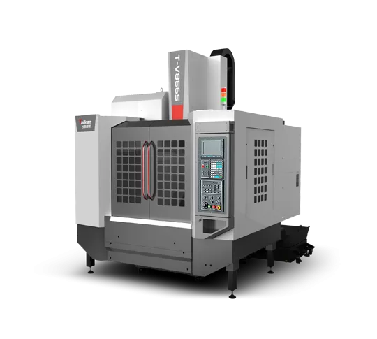
For demanding machining or heavier components, machine structure and guideway selection become increasingly important. A Linear guide type vertical machining center can provide an effective solution where rapid movement, positioning speed, and general precision machining are important, while other machine structures may be selected when greater heavy-cutting requirements dominate the process.
Do Not Oversize a VMC Without a Production Reason
Purchasing a larger machine can appear to provide additional flexibility, but excessive capacity also has disadvantages.
A larger machining center generally requires more factory floor space. Longer axis movements may increase non-cutting travel, and larger moving structures can affect acceleration characteristics. Tool and fixture access may also become less convenient for relatively small parts.
If a manufacturer primarily produces compact aluminum components requiring fast milling, drilling, and tapping, a machine optimized for lighter and faster cutting may be more productive than an oversized heavy machining center.
For these applications, a Light Cutting vertical machining center can be evaluated according to the actual workpiece size, material, cutting load, cycle-time objective, and required machining operations.
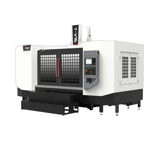
The correct machine is therefore not automatically the one with the greatest travel. Machine size should support the workpiece and process without creating unnecessary capacity.
Consider How Many Parts Will Be Loaded per Setup
Production quantity can change the required machine size even when the component drawing remains exactly the same.
A job shop producing ten components may machine one part at a time. A factory producing several thousand identical components may prefer a fixture that holds two, four, or more parts in each cycle.
Multi-part fixturing can reduce loading frequency and allow the spindle to machine several components before the operator opens the machine door. However, it also increases table-space and travel requirements.
When calculating machine size, manufacturers should therefore evaluate both:
Minimum capacity needed to machine one component
Preferred capacity needed to achieve the target production rate
This distinction helps prevent choosing a machine that can technically produce the part but cannot achieve the desired batch productivity.
Allow Reasonable Capacity for Future Workpieces
A machining center is usually purchased for several years of production, so machine selection should not be based exclusively on today's largest part.
Manufacturers should review customer development plans, product families, future contract opportunities, and expected changes in fixture design.
Some additional capacity can be useful, particularly if future components are expected to become slightly larger. However, future-proofing should remain realistic. Buying a substantially larger machine for hypothetical work that may never arrive can reduce return on investment.
A practical approach is to select a machine that comfortably accommodates current representative parts and provides a reasonable reserve for foreseeable workpieces rather than planning for every possible future component.
Match Travel With Spindle and Cutting Requirements
Machine travel should not be evaluated separately from cutting performance. Two machines with similar working envelopes may be designed for very different applications.
Manufacturers should also consider:
Workpiece material
Required spindle speed
Required spindle torque
Tool diameter and length
Depth of cut
Metal-removal requirements
Surface-finish requirements
Expected cycle time
High-speed machining of aluminum may prioritize spindle speed and rapid axis movement, while heavy steel machining may place greater emphasis on rigidity and low-speed torque. Machine capacity should therefore be evaluated as a complete system rather than through table dimensions alone.
Use Representative Part Drawings Before Making the Final Decision
The most reliable way to select machine travel is to evaluate several representative components rather than relying on a general description of production.
A useful machine-selection package should include:
2D or 3D workpiece drawings
Material specifications
Blank dimensions
Finished-part dimensions
Fixture concept
Machined surfaces
Tolerance requirements
Tooling information
Expected annual quantity
Target cycle time
With this information, the required working envelope can be checked against the real machining process. It also becomes easier to identify whether additional travel provides useful production flexibility or simply increases machine size.
FAQ
Should VMC axis travel be larger than the workpiece?
In most cases, yes. Additional travel is normally required for fixtures, clamping space, tool approach, edge machining, and safe movement around the component. The necessary margin depends on the workpiece and fixture design.
Is a larger VMC always better?
No. A larger machine provides additional capacity but may also increase investment, floor-space requirements, and unnecessary non-cutting movement. Machine size should be matched to actual and foreseeable workpieces.
How do I determine the required Z-axis travel?
Consider the workpiece height, fixture height, tool and holder length, machining depth, spindle-to-table clearance, and the space required for safe tool approach and retraction.
Should fixture weight be included when checking table capacity?
Yes. Table load should include the workpiece, fixture, vises, rotary devices, clamping components, and all other equipment mounted on the machine table.
How much extra machine capacity should I leave for future production?
There is no universal percentage. The most practical approach is to review expected future part families and select reasonable additional capacity without purchasing a machine substantially larger than foreseeable production requires.
Can two VMCs with the same travel perform differently?
Yes. Machines with similar axis travel can differ in spindle characteristics, structural rigidity, guideway design, rapid traverse, table load, tool capacity, and control configuration. Travel is only one part of machine selection.
Conclusion
Choosing the correct VMC table size and axis travel begins with understanding the complete machining setup rather than simply matching machine travel to finished-part dimensions. Workpiece size, fixture dimensions, tool clearance, table load, production quantity, multi-part fixturing, spindle requirements, and future parts should all be evaluated together.
The best machine is not necessarily the smallest model that can fit the component or the largest model available within the budget. A well-matched vertical machining center should provide enough usable working space for reliable production while avoiding unnecessary capacity. By using representative part drawings and evaluating the complete machining process before purchase, manufacturers can select a machine that supports both production efficiency and long-term manufacturing flexibility.


